MPLS Networks
Create MPLS (Multiprotocol Label Switching) topologies and create virtual circuits between network interfaces.
 |
|---|
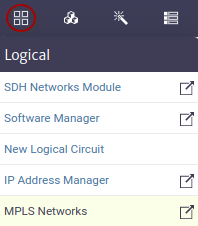
| Figure 1. MPLS Module |
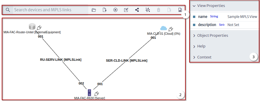
Figure 2 shows an example MPLS view.
 |
|---|
| Figure 2. Example MPLS View |
- Tools.
- Canvas.
- View Options Panel and Object Options Panel.
Tools
 |
|---|
| Figure 3. Tools |
Figure 3 shows the tools to manage the MPLS views.
| Tool | Description |
|---|---|
 | Open view |
 | New view |
 | Remove view |
 | Add existing devices and MPLS links to the view |
 | New MPLS link |
 | Detect MPLS link between nodes |
 | Remove from database and view |
 | Remove from view |
 | Export as image |
Creating a View
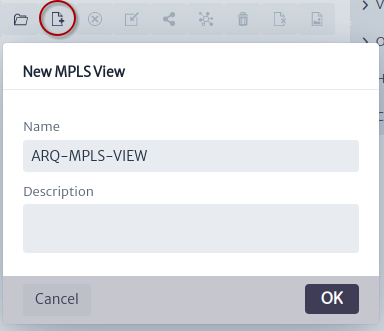
To create a new view click on the New MPLS view tool Figure 4.
 |
|---|
| Figure 4. New MPLS view window |
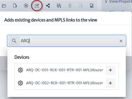
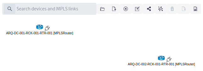
Once the view is created, two routers will be added Figure 5, these are the ones that were used in the physical circuit that was built in the connectivity manager chapter.
 |
|---|
| Figure 5. Add existing devices |
Figure 6 shows the view with the two MPLS routers.
 |
|---|
| Figure 6. View with two MPLSRouters |
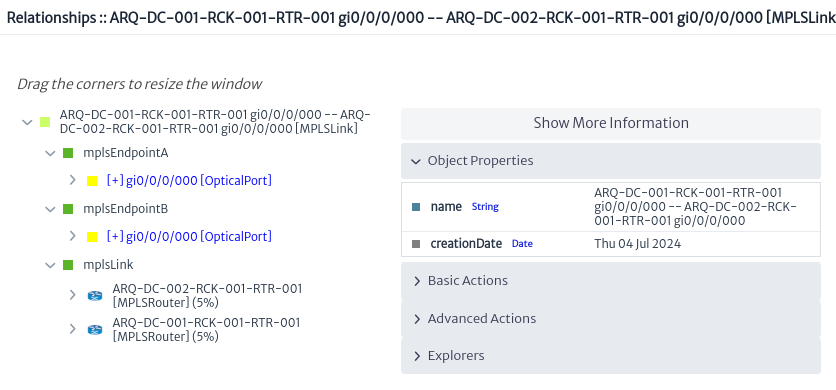
In the chapter about New Logical Circuit, an MPLS Link Figure 7 was created that we will add to this view.
 |
|---|
| Figure 7. Existing MPLS Link |
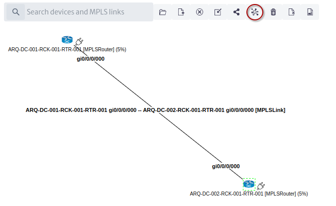
Using the MPLS link detection tool between nodes Figure 8.
 |
|---|
| Figure 8. View with MPLSLink |
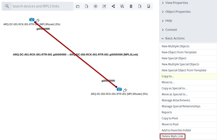
Module Actions
Delete MPLS Link
Applies to object instances of
MPLSLinksubclasses.
 |
|---|
| Figure 9. Delete MPLS Link |
Relate to VLAN
Applies to object instances of
GenericPortsubclasses.
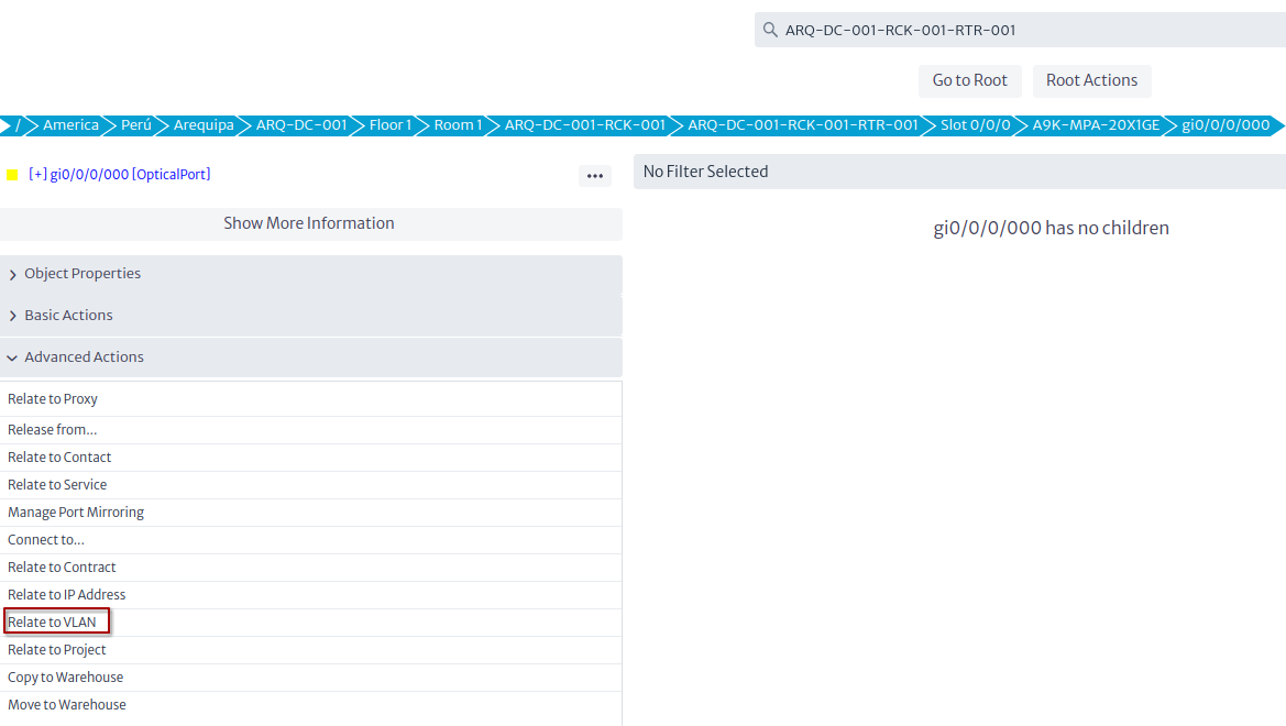 |
|---|
| Figure 10. Relate to VLAN |