New Logical Circuit
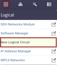
Creates new logic circuits given the type and the endpoints. The access method is shown in Figure 1.
 |
|---|
| Figure 1. New Logical Circuit module |
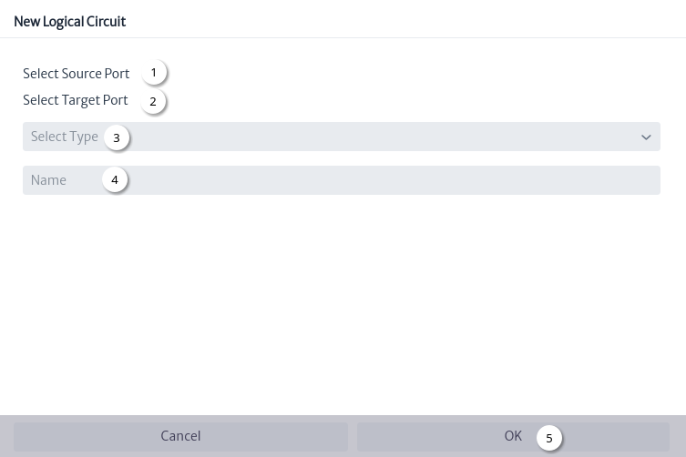
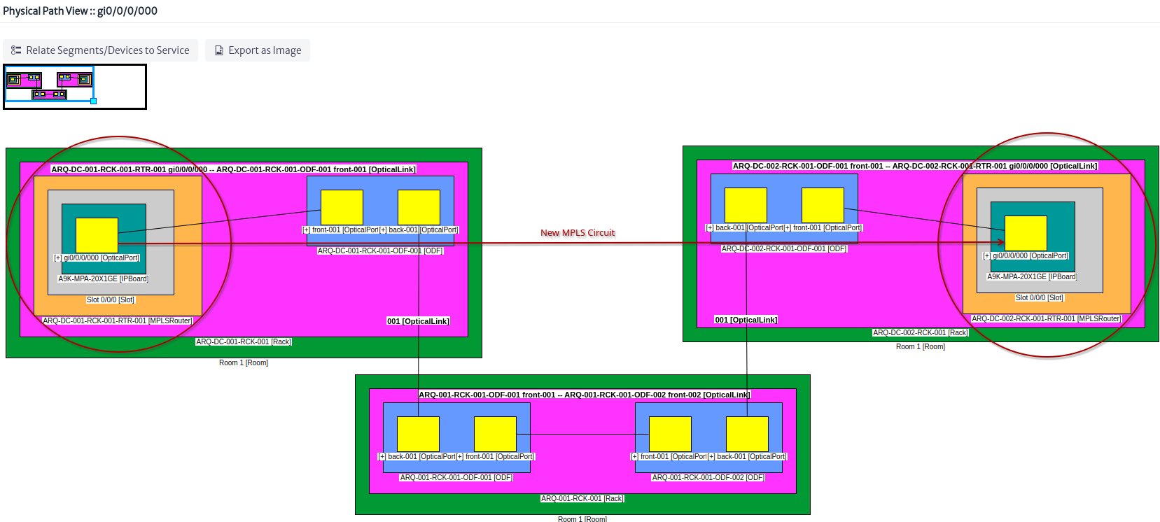
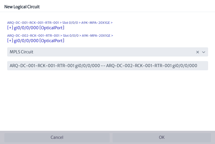
Figure 2 shows the step by step to configure the new logical circuit. For this example, the physical circuit Figure 3 built in the chapter of the Connectivity Manager module will be used.
 |
|---|
| Figure 2. New logical circuit window |
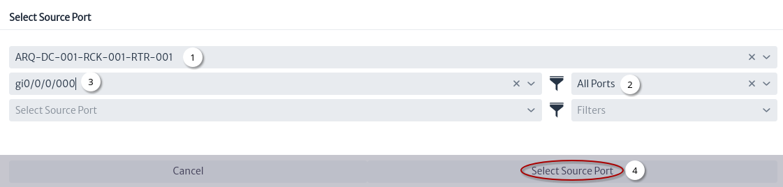
- Select source port Figure 4.
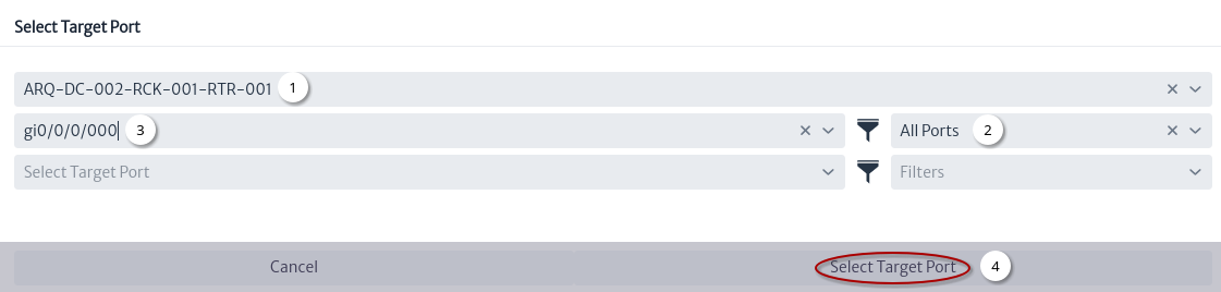
- Select target port Figure 5.
- Select logical circuit type Figure 6.
- Automatically generated name Figure 6.
- Click on the
OKbutton.
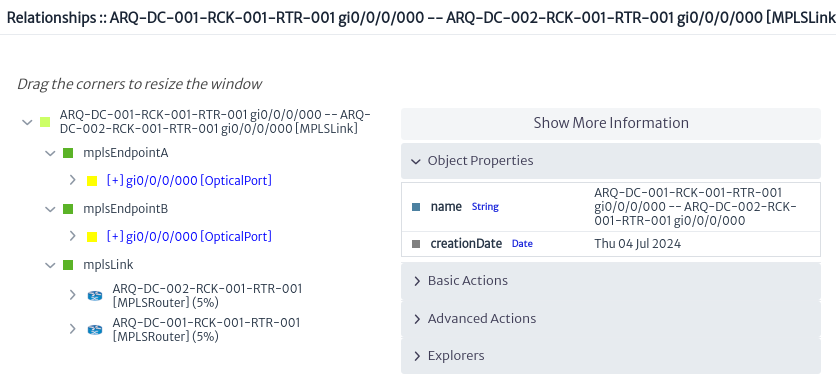
Using the Navigation module you can search for the new logical circuit the Figure 7 shows the relationships explorer.
 |
|---|
| Figure 3. Physical circuit |
 |
|---|
| Figure 4. Select source port |
 |
|---|
| Figure 5. Select target port |
 |
|---|
| Figure 6. Configuration of the new logical circuit |
 |
|---|
| Figure 7. New logical circuit relationships |