Connectivity Manager

The connectivity manager module helps with the creation of physical and logical circuits. The access method is shown in Figure 1.

Connectivity manager module
Figure 1. Connectivity manager module

Clicking on the module will open a window Figure 2.

Connectivity manager window
Figure 2. Connectivity manager window
  1. Link to create a New Object Figure 3.
  2. Link to Template Manager module.
  3. Link to Navigation module
Select new object parent
Figure 3. Select new object parent

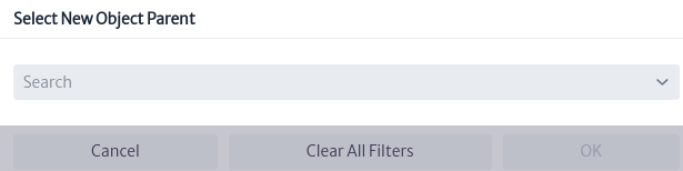
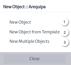
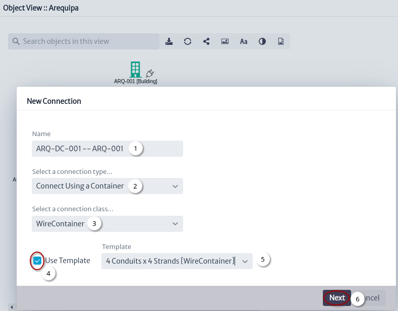
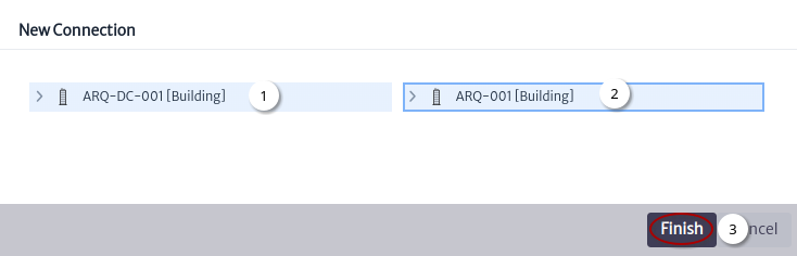
Figure 3 shows the window that appears after clicking on the New Object link, in which a parent is selected for the new object and then an action is chosen for the creation Figure 4.

New Object window
Figure 4. New object window

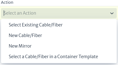
Figure 4 shows the basic actions to create an object:

  1. New Object
  2. New Object from Template
  3. New Multiple Objects

Creating a Physical Circuit

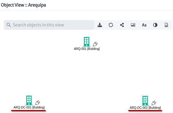
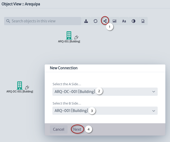
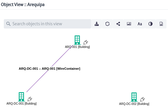
The goal of this section is to create a physical circuit between two routers that are located in two data centers (DC) Figure 5.

Initial object view
Figure 5. Initial object view

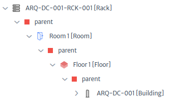
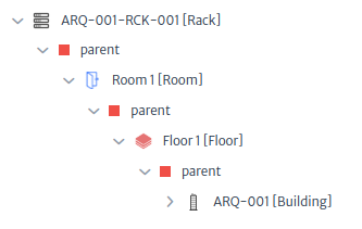
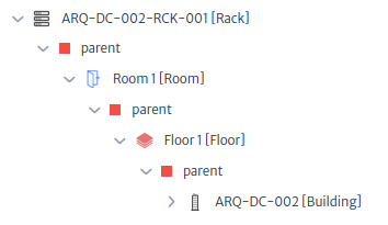
The Building objects are within a City object and each one has a Rack object Figure 6, Figure 7 and Figure 8.

Parents of Rack in Data Center 001
Figure 6. Parents of Rack in Data Center 001
Parents of Rack in Building 001
Figure 7. Parents of Rack in Building 001
Parents of Rack in Data Center 002
Figure 8. Parents of Rack in Data Center 002

Each Rack object inside the Building object contains the equipment to be connected. Below are simple rack views of the racks that will be used:

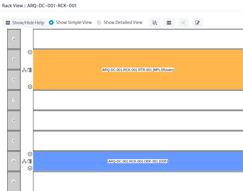
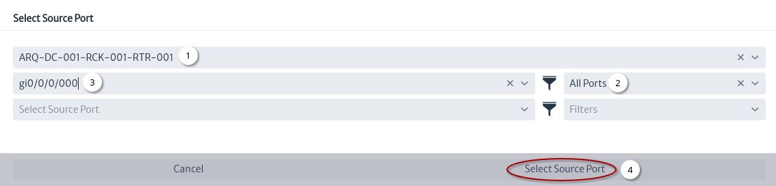
  • The Rack object in data center 001 contains an ODF object and a MPLSRouter object of which one of its ports will be used as the start of the physical circuit Figure 9.
Simple Rack View of Rack in Data Center 001
Figure 9. Simple Rack View of Rack in Data Center 001
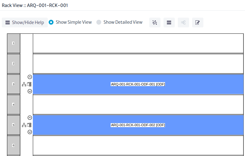
  • The Rack object in building 001 contains two ODF objects used simply to reach data center 002 Figure 10.
Simple Rack View of Rack in Building 001
Figure 10. Simple Rack View of Rack in Building 001
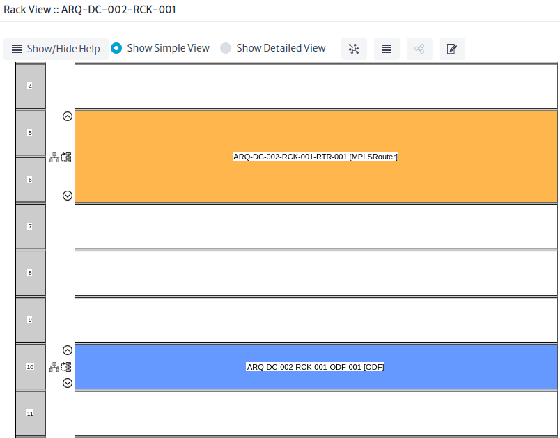
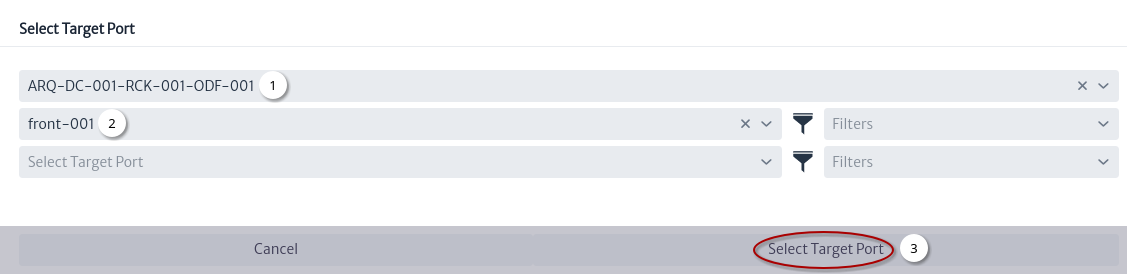
  • The Rack object in data center 002 contains a ODF object and a MPLSRouter object of which one of the ports will be used as the end of the physical circuit Figure 11.
Simple Rack View of Rack in Data Center 002
Figure 11. Simple Rack View of Rack in Data Center 002

New Connection

Before creating the physical circuit using the object view, a connection will be created between data center 001 and building 001.

Figure 12 shows how the creation starts.

New connection window
Figure 12. New connection window
  1. Click on the Connect button.
  2. Select side A of the connection.
  3. Select side B of the connection.
  4. Click on the Next button.

Figure 13 shows the definition of the characteristics of the new connection.

Details of new connection
Figure 13. Details of new connection
  1. Set connection name 1.
  2. A cable will be used to connect the two buildings.
  3. Set the connection class.
  4. Check to use a cable template. See the Template Manager module.
  5. Select a template.
  6. Click on the Next button.

Figure 14 shows the selection of the connection endpoints.

New connection endpoints
Figure 14. New connection endpoints
  1. Select the endpoint A of the connection.
  2. Select the endpoint B of the connection.
  3. Click on the Finish button.

Figure 15 shows the new connection.

Object view with new connection
Figure 15. Object view with new connection

Connectivity Manager Window

Once the initial state of the network that will be used is known, we begin with the creation of the physical circuit Figure 16.

Connectivity Manager window
Figure 16. Connectivity Manager window
  1. Button to select the source port Figure 17.
  2. Button to select the source port Figure 18.
  3. Type of action to execute between ports Figure 19 and Figure 20.
  • Figure 17 shows the selection of the port from where the physical circuit starts.
Select source port
Figure 17. Select source port
  1. The MPLSRouter object is searched using its name.
  2. Using filters, all ports within the Router are listed. See Filters module.
  3. Select one of the ports.
  4. Click the button.
  • Figure 18 shows the selection of the target port.
Select target port
Figure 18. Select target port
  1. The ODF object is searched using its name.
  2. Select one of the ports.
  3. Click the button.
  • Figure 19 shows the actions that will be taken between the ports.
Connectivity manager actions
Figure 19. Connectivity manager actions

Actions

New Cable/Fiber
  • Figure 20 shows the action that will be taken between the ports.
New fiber window
Figure 20. New fiber window
  1. Automatically generated name1.
  2. Select link type.
  3. Click the button.

Figure 21 shows the first connection.

First connection
Figure 21. First connection
New Mirror

Figure 22 shows the steps to execute the action of a new mirror between two ports of a ODF.

New mirror
Figure 22. New mirror
  1. Select target port.
  2. Select New Mirror action.
  3. Choose mirror type.
  4. Click the button.
Select Existing Cable/Fiber
Select existing cable action
Figure 23. Select existing cable action
  1. Select target port.
  2. Select Existing Cable/Fiber action.

Figure 24 shows the action to use an existing cable, the cable that was created in the New Connection section will be used.

Select existing cable window
Figure 24. Select existing cable window
  1. Select the cable.
  2. Select the tube.
  3. Select fiber.
  4. Click the button.
Select a Cable/Fiber in a Container Template

Before creating a cable using templates, some mirrors and links were created Figure 25.

Select a Cable/Fiber in a Container Template
Figure 25. Select a Cable/Fiber in a Container Template action
  1. New mirrors and links added. See New Mirror and New Cable/Fiber actions.
  2. Select target port.
  3. Select a Cable/Fiber in a Container Template action.

Figure 26 shows the creation of a cable between building 001 and data center 002 using templates. See Template Manager

Select a Cable/Fiber in a Container Template window
Figure 26. Select a Cable/Fiber in a Container Template window
  1. Select endpoint A of the cable.
  2. Select endpoint B of the cable.
  3. Select the class.
  4. Set the cable name1.
  5. Select cable template.
  6. Select a tube.
  7. Select a fiber.
  8. Click the button.

Physical Circuit

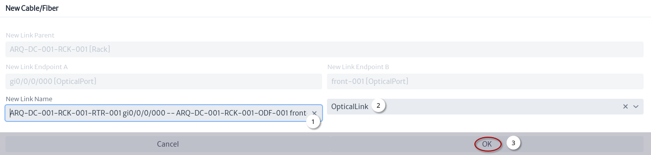
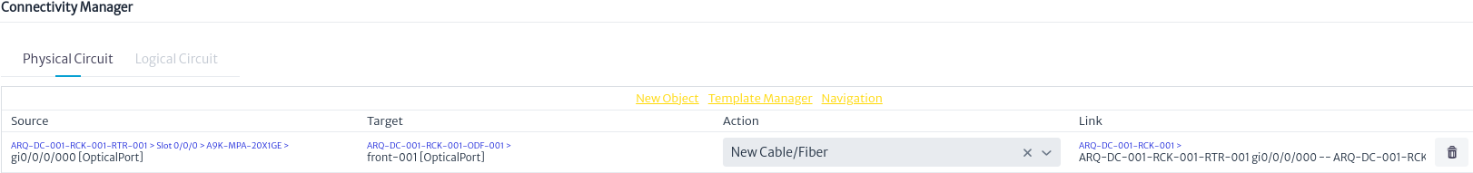
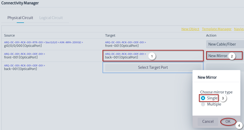
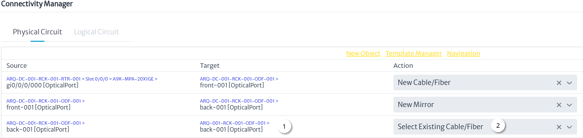
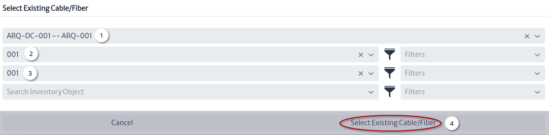
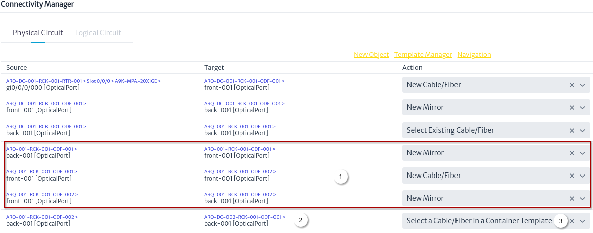
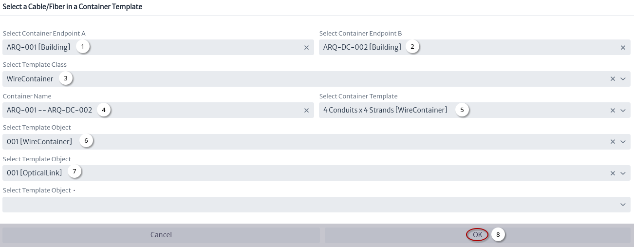
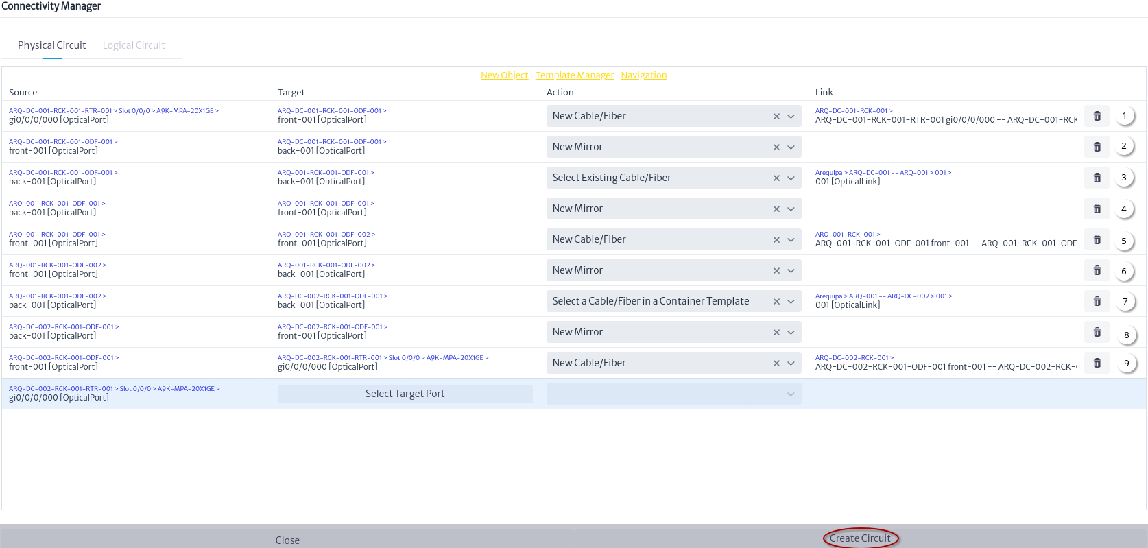
Figure 27 shows the physical circuit from one port of a MPLSRouter in data center 001 to the other port in a MPLSRouter in data center 002.

Physical circuit
Figure 27. Physical circuit

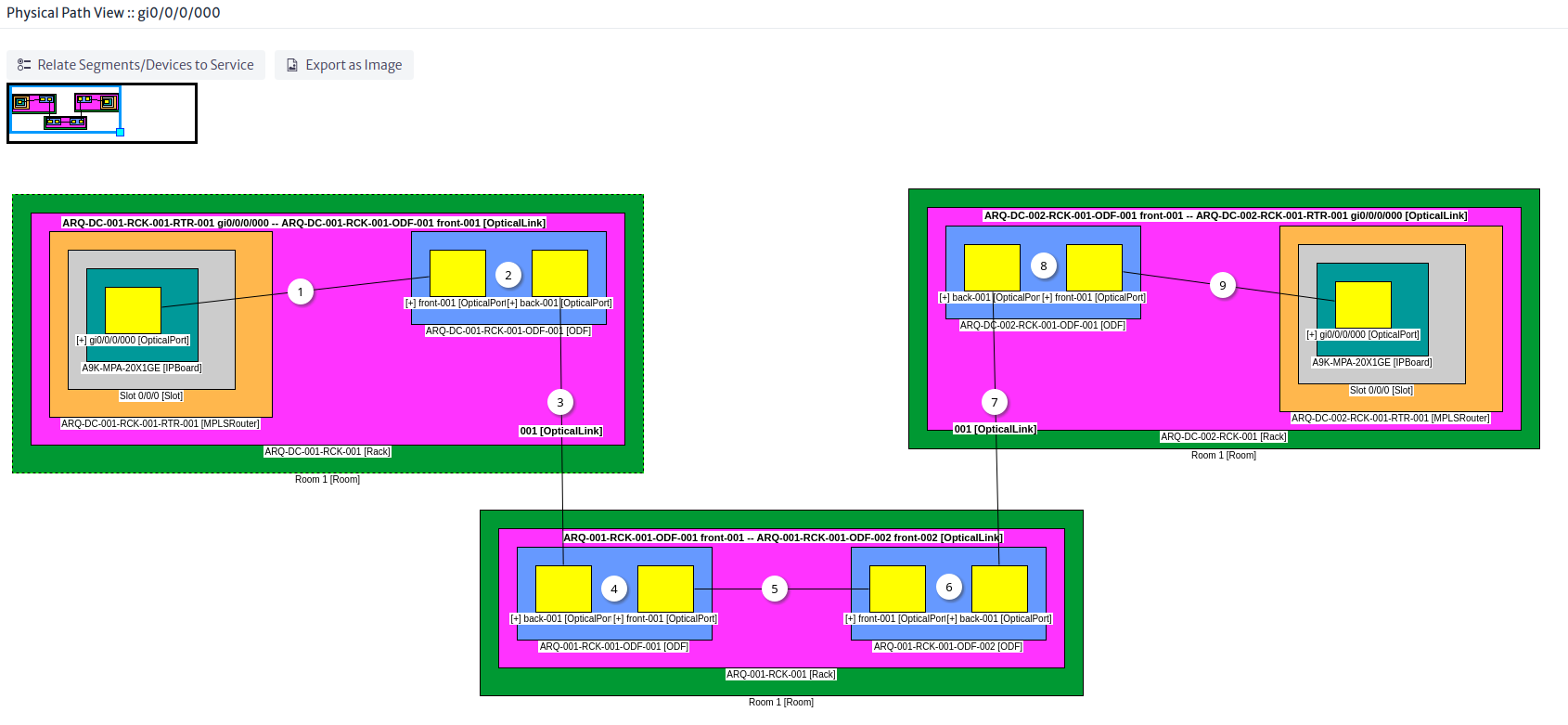
Once the physical circuit has been created, you can see the physical path of the MPLSRouter port in the data center 001 Figure 28.

Physical circuit
Figure 28. Physical circuit

Note The numbering in Figures 27 and 28 is used to show different perspectives of the same physical circuit. For example (1) is the fiber connected from a MPLSRouter port to an ODF port.

Creating a Logical Circuit

A logical circuit is a point-to-point connection and is used to represent last mile OSP circuits.

Note To create other types of logic circuits see the New Logic Circuit module.

New Service

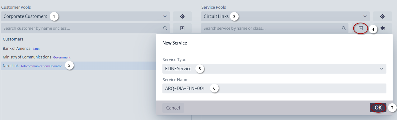
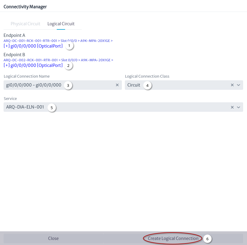
Before creating the logical circuit, the service to which it will be associated will be created. Figure 29 shows the step by step to create a service using the Service Manager module.

New Service
Figure 29. New Service
  1. Select the customer pool.
  2. Select the customer.
  3. Select the service pool.
  4. Click on the New Service button.
  5. Choose the type of service.
  6. Set the service name1.
  7. Click on the OK button.

Create Logical Connection

Logical connection are used to represent point-to-point connections like those used in modules SDH and MPLS.

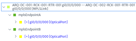
The logical connection created in this module are similar to MPLS Figure 30.

MPLS relationships
Figure 30. MPLS relationships

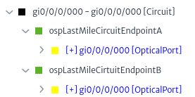
The difference with MPS is the objects and relationships used Figure 31.

Last mile circuit relationships
Figure 31. Last mile circuit relationships

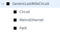
The types of logical connections are the subclasses of GenericLastMileCircuit to add more options that adapt to your needs, just create subclasses using the Data Model Manager, for example MetroEthernet.

Custom GenericLastMileCircuit subclasses
Figure 32. Custom GenericLastMileCircuit subclasses

Notes

  • Logical connections were designed for last mile services, however currently they are used interchangeably to represent logical circuits.
  • It is possible that the model will be simplified in the future, it is recommended to use Circuit to facilitate the migration.

Figure 33 shows the step by step to create a logical connection.

Create Logical Connection
Figure 33. Create Logical Connection
  1. Select source port.
  2. Select target port.
  3. Automatically generated name1.
  4. Select logical connection class.
  5. Search service by name or class.
  6. Click on the Create Logical Connection button.

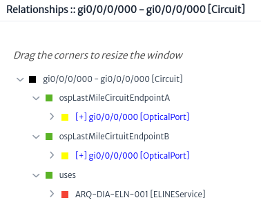
Using the Navigation module you can search for the new logical connection the Figure 34 shows the relationships explorer for the created logical connection.

Logical connection relationships
Figure 34. Logical connection relationships
1

Object names in Kuwaiba should use a naming convention to facilitate their management.