The Layout editor is a module that allows us to design the physical view of the elements hosted in a Rack and is used in the Rack view.
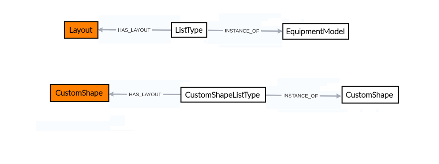
Figure 1 illustrates the module’s structure. When creating a layout in the application and linking it to a listType item, this is done through the HAS_LAYOUT relationship. The type of the listType is determined by the class it is associated with via the INSTANCE_OF relationship. In the example, the listType is of type EquipmentModel. Similarly, when creating a customShape, a corresponding listType with the same name is automatically created and linked through the HAS_LAYOUT relationship. ListTypes associated with customShapes are, by default, of type CustomShape.
 |
|---|
| Figure 1. Layout editor structure |
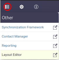
This module is part of the Other category, as shown in Figure 2.
 |
|---|
| Figure 2. Layout editor module |
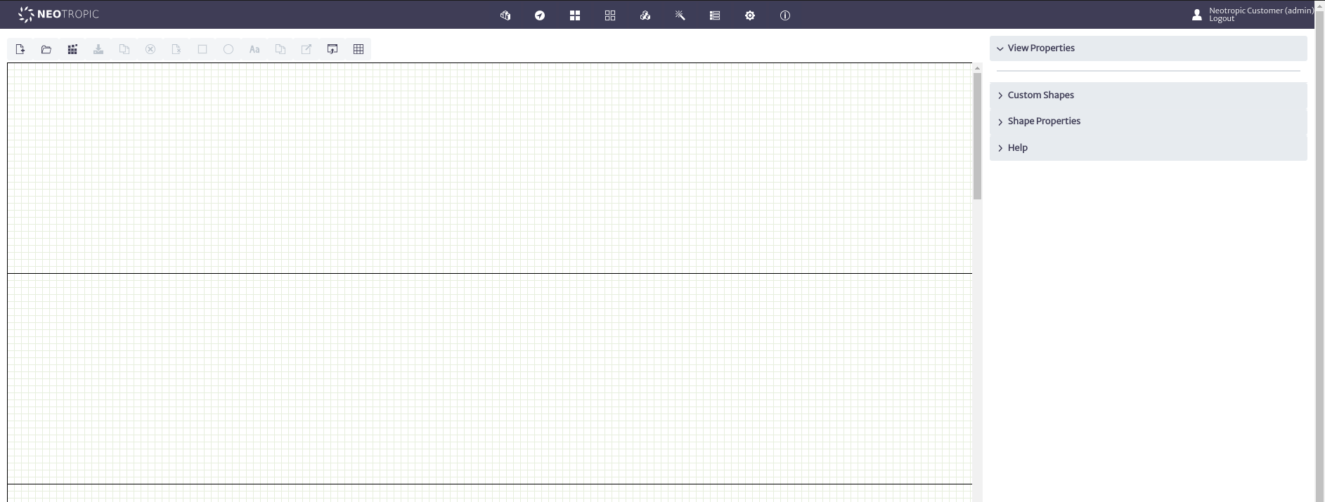
Once opened, we will see the main window of the module, as shown in Figure 3. From here we can see the canvas to create layouts.
 |
|---|
| Figure 3. Queries manager main window |
To design layouts, the module offers various tools, which can be found in the toolbar located at the top of the canvas, as shown in Figure 4.
 |
|---|
| Figure 4. Layout designer tools |
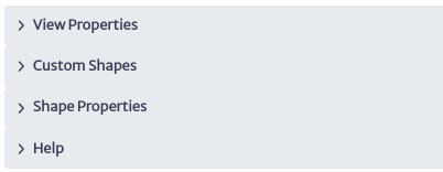
You will also find the properties panel on the right side of the canvas, which allows you to interact with the topology objects, as shown in Figure 5.
 |
|---|
| Figure 5. Properties panel |
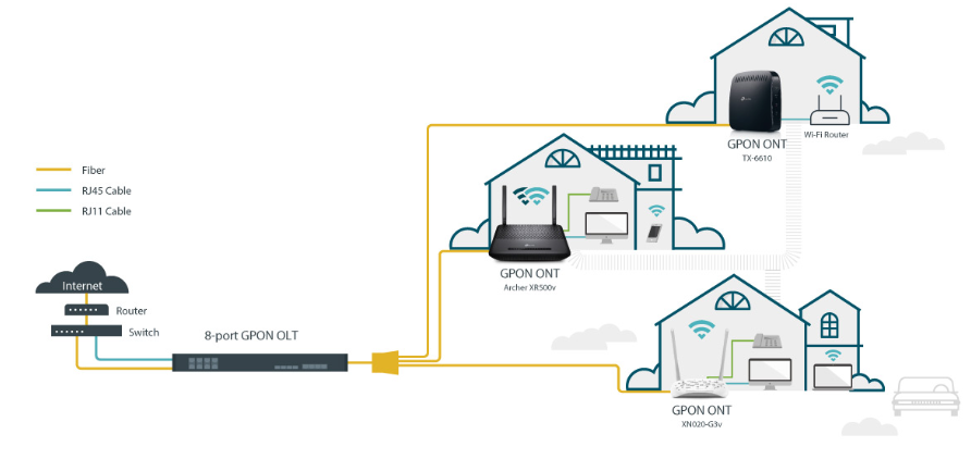
As an example, let's recreate the design of the GPON OLT P1201-08 from TPLINK used in a GPON network as shown in Figure 6. In this network, we have the central office where our OLT is located. A primary splitter is used to connect the ONTs located in customers' homes. In this case, we will focus on the design of the OLT hosted in the rack. If you want to create full representations of a network, please refer to the Topology Designer module for more details.
 |
|---|
| Figure 6. Red GPON diagram |
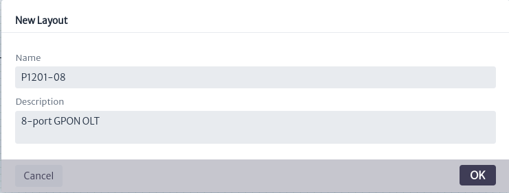
To start, you must create a new layout using the  button. The window shown in Figure 7 will open. Enter the name and description, then click OK.
 |
|---|
| Figure 7. Window create layout |
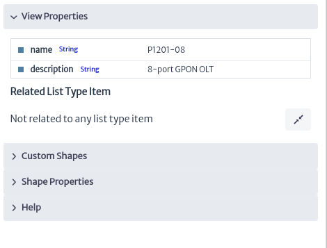
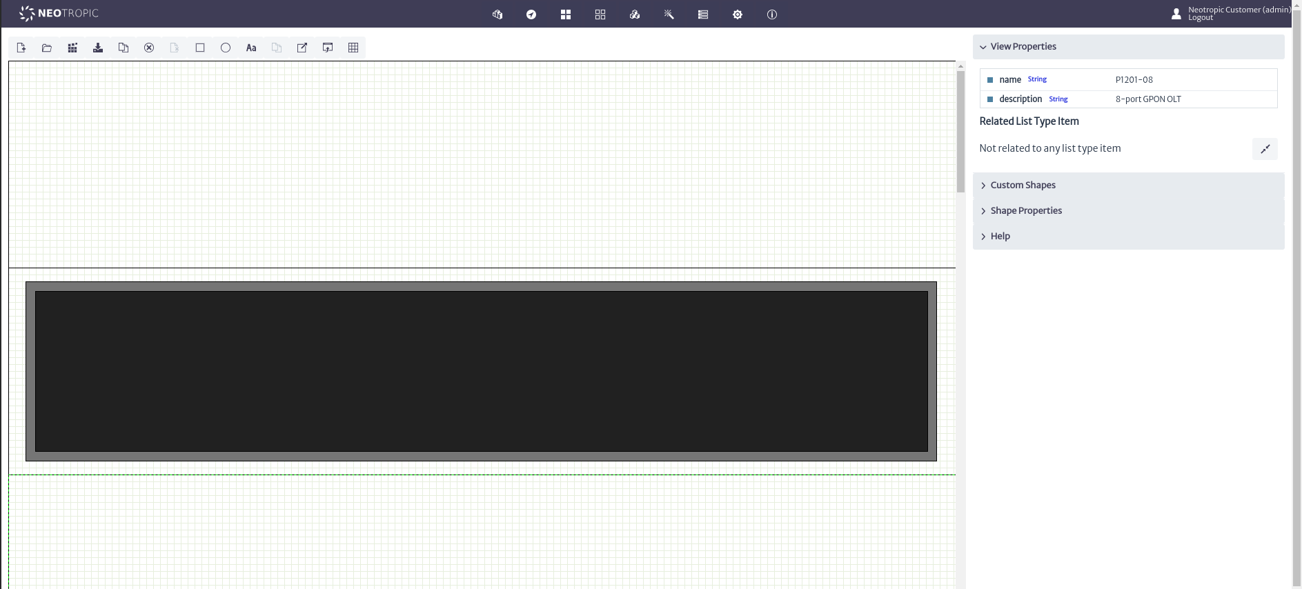
When you create a layout, you can see and edit its properties in View Properties in the properties panel, as shown in Figure 8.
 |
|---|
| Figure 8. View properties |
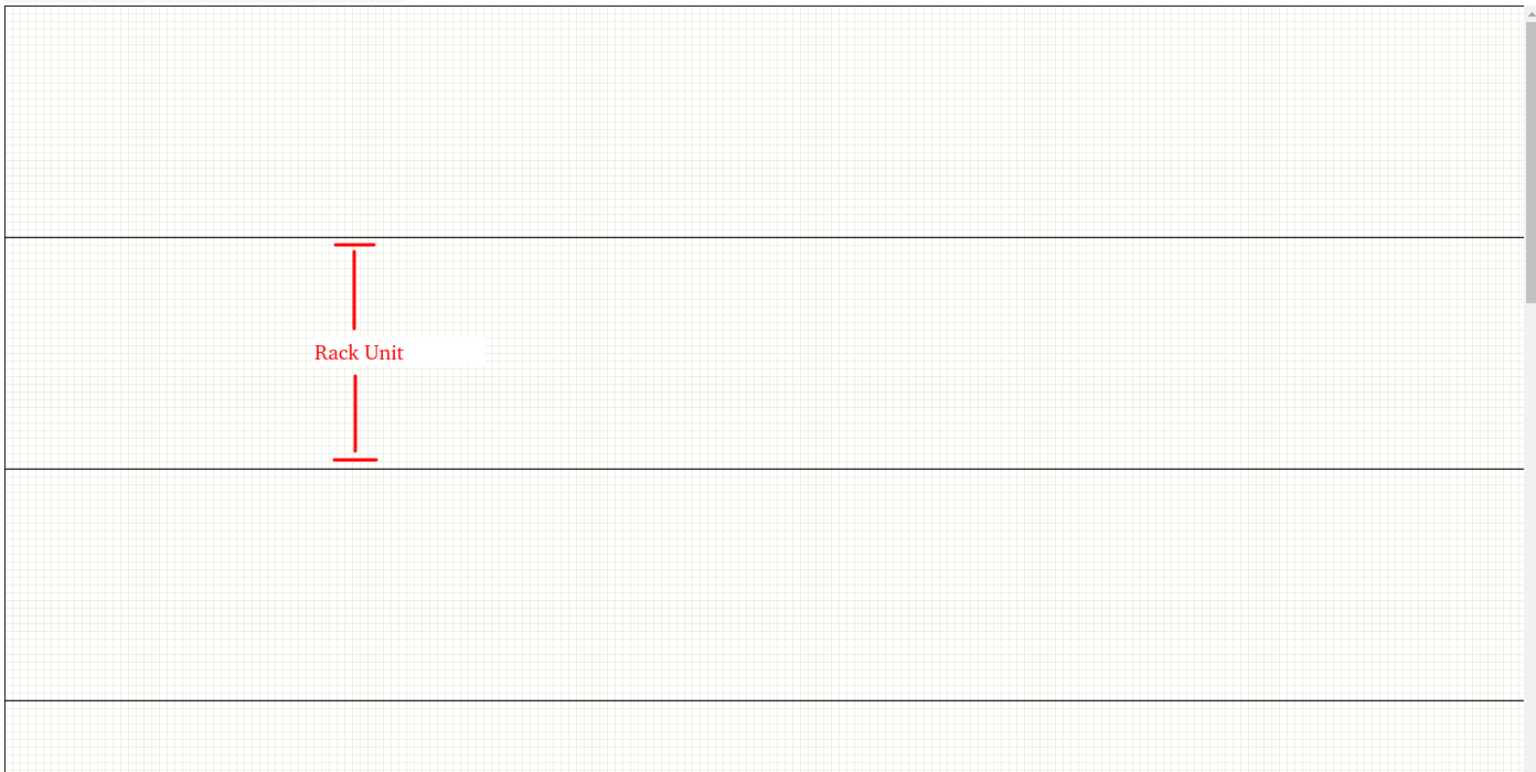
Once the layout is created, we proceed to add the elements on the canvas, as shown in Figure 9. The canvas has 14 delimited spaces to represent the rack units in order to facilitate the placement and sizing of the elements.
 |
|---|
| Figure 9. Canvas division |
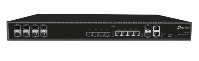
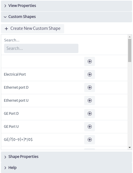
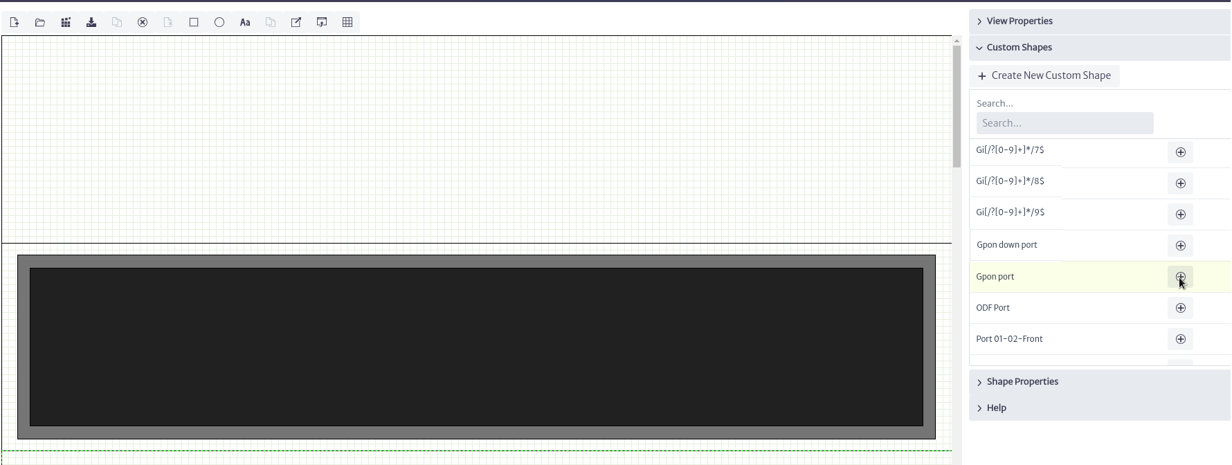
To start designing the GPON OLT P1201-08 shown in Figure 10, we can use the custom shapes available in the application. Custom shapes are templates of common elements such as electrical ports, internet ports, etc. To access them, click on Custom Shapes in the properties panel shown in Figure 11.
 |
|---|
| Figure 10. GPON OLT P1201-08 |
 |
|---|
| Figure 11. Custom Shapes |
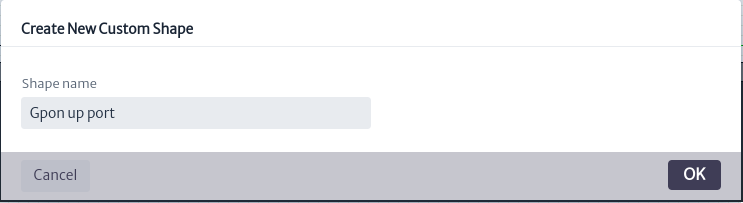
By default, a wide variety of templates are available; however, you can create your own templates according to your needs. In this case, we will create the templates. Use the button shown in Figure 11. The window in Figure 12 will open. Enter a name and click OK.
 |
|---|
| Figure 12. Create custom shape window |
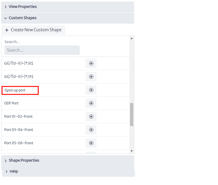
The created template will appear in the list of available templates as shown in Figure 13; however, at this moment it is not possible to use it because it is empty.
 |
|---|
| Figure 13. New Custom shape |
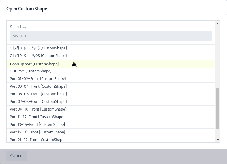
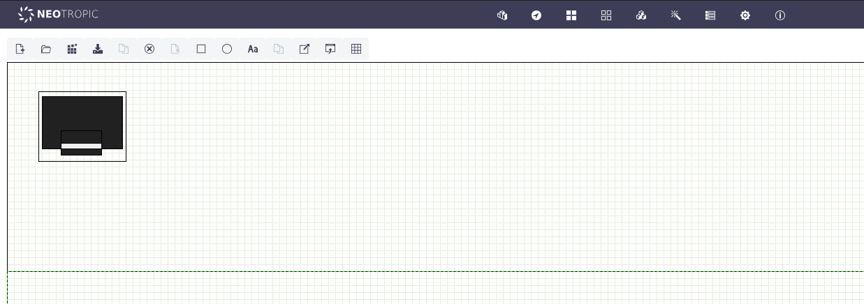
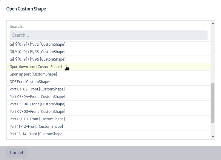
To create its content, we need to open it using the button located in the design toolbar shown in Figure 4. When used, the custom shapes selection window will open. We search for the created template and Click on it as shown in Figure 14.
 |
|---|
| Figure 14. Select custom shape window |
When doing so, you will notice that several tools on the toolbar seen in Figure 4 will be enabled, as shown in Figure 15.
 |
|---|
| Figure 15. Enabled layout designer tools |
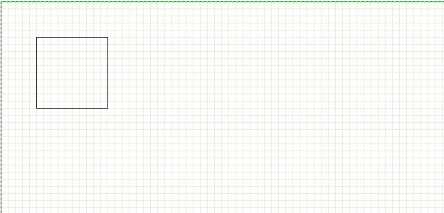
Next, we will proceed to create the custom shapes that will represent the GPON ports of our OLT. To do this, we use the shapes provided by the module, as shown in Figure 16. We have rectangles, circles and labels available; in our case, we will add a rectangle using as shown in Figure 17.
 |
|---|
| Figure 16. Add shapes actions |
 |
|---|
| Figure 17. Add shape |
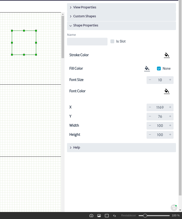
By clicking on the shape we added will enable tools  that allows you to remove the selected shape from the canvas and
  that allows you to create a copy of the element. In the properties panel it will show the actions available to customize the properties of the shapes according to our needs. Among these actions, you can modify the background color, outline color, font color, font size, width and height, and more, as shown in Figure 18.
 |
|---|
| Figure 18. Shape properties |
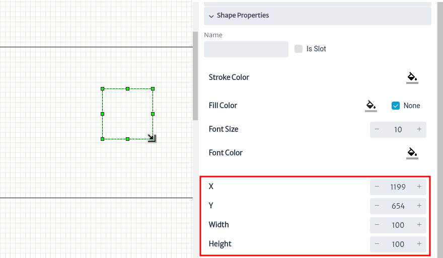
In addition to this, you can see guides appear to change the dimensions of the shape. When you hover over the element, it will change as shown in Figure 19. Click and drag to adjust it to the desired size. You can also use the tools highlighted in the properties panel to adjust the width, height, and position of the shapes.
 |
|---|
| Figure 19. Change shape size |
After finishing modeling the OLT port as shown in Figure 20, you can use the button  to save your design.
 |
|---|
| *Figure 20. OLT GPON port * |
With the template for the upper ports ready, we can now proceed to create the template for the lower ports. To do this, we can use the recently created template as a base by exporting its design using the button  . This will generate an XML document for download, as shown in Figure 21.
 |
|---|
| Figure 21. Export shape |
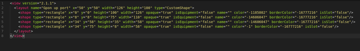
The generated XML file contains tags that represent the custom shape, as shown in Figure 22. We can modify it to create a new template. To do this, change the value of the name attribute in the layout tag from Gpon up port to Gpon down port, as seen in the second line of Figure 22.
 |
|---|
| Figure 22. XML shape file |
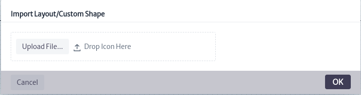
Once the file is modified, use the button  to open the window for importing layouts, as shown in Figure 23. Press Upload File, select the previously modified view file, and click OK.
 |
|---|
| Figure 23. Import layout/shape window |
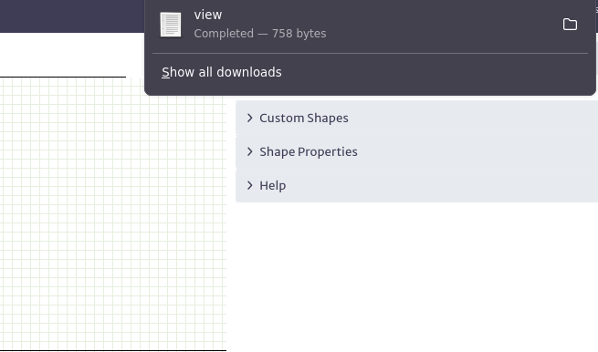
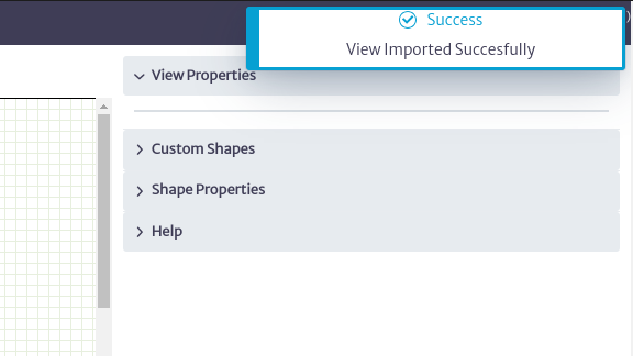
You will be notified that the custom shape was imported successfully, as shown in Figure 24. It will appear in the list of available custom shapes, as seen in Figure 25.
 |
|---|
| Figure 24. Imported shape |
 |
|---|
| Figure 25. Shape imported available |
Once the template is modified to represent the lower ports of the OLT, save the changes. The result can be seen in Figure 26.
 |
|---|
| Figure 26. Gpon down port |
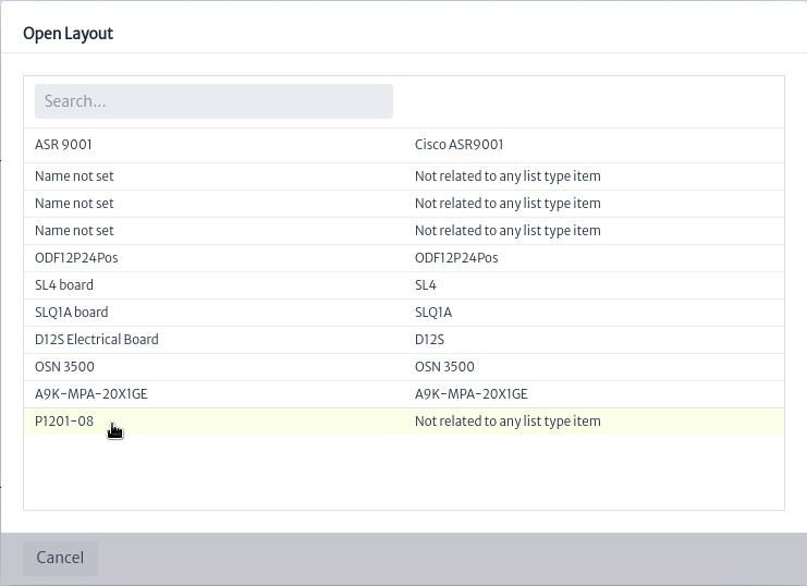
Once the custom shapes for the OLT ports are completed, proceed with its design by opening the previously created layout. To do this, click the button  , which will open the layout selection window as shown in Figure 27. Click on the layout to open it.
 |
|---|
| Figure 27. OPen layout window |
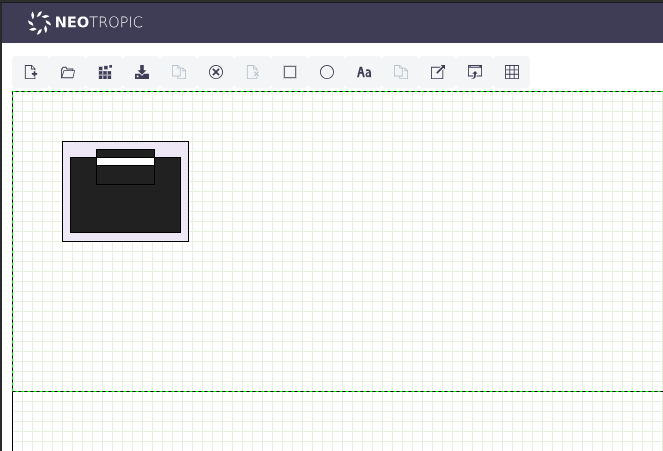
Once opened, we start by creating the chassis for our OLT in the desired rack slot, represented by the divisions on the canvas as shown in Figure 28. For our example, we use the second space on the canvas, which represents the second slot of the rack.
 |
|---|
| Figure 28. Olt Chasis |
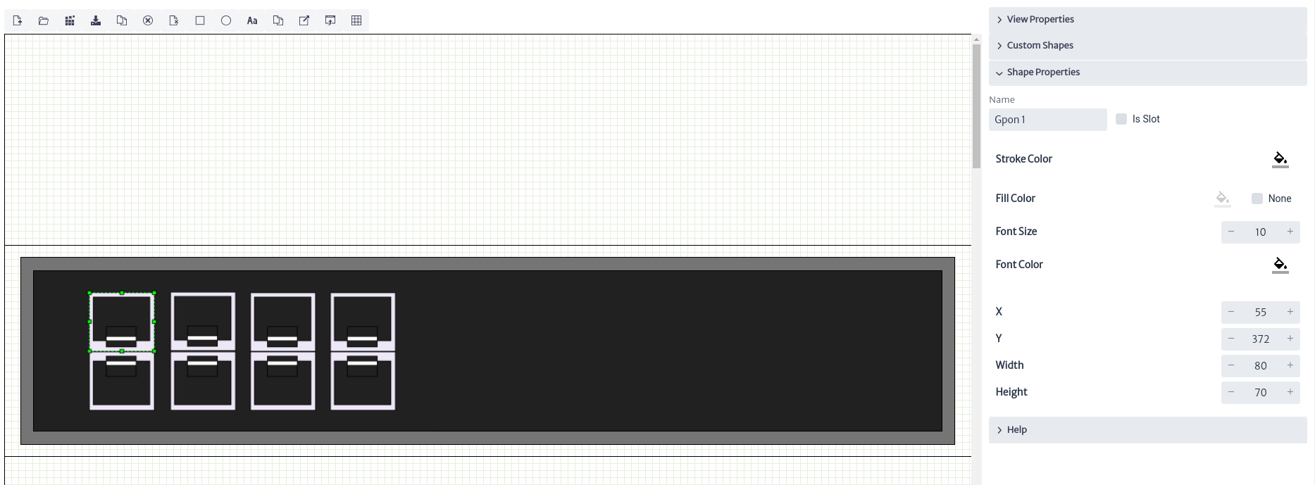
Next, we proceed to place the OLT ports according to the design in Figure 10, where we find the upstream Gigabit ports, management ports, GPON ports, etc. We will use the custom shapes previously created and those available in the application. To do this, use the button for the custom shape you want to use, to add elements to the layout as shown in Figure 29.
 |
|---|
| Figure 29. Add custom shape |
When adding the ports, assign the names of the custom shapes, placing the odd-numbered elements on the top and the even-numbered elements on the bottom, as shown in Figure 30.
Note
Pay close attention to the names assigned to the elements, as these will be used in the rack views for connection assignment, explained in detail in the Rack View section.
 |
|---|
| Figure 30. Add GPON ports |
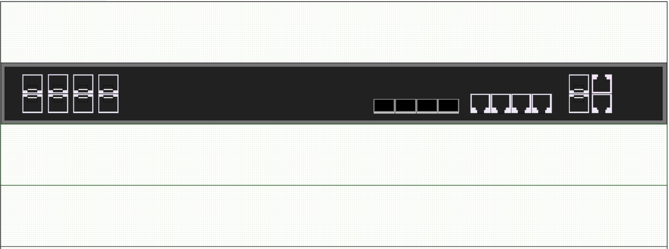
At the end, you will get something similar to what is shown in Figure 31.
 |
|---|
| Figure 31. OLT P1201-08 |
Finally, to visualize how the designed device would be contained in the rack, use the Rack View. To view the layout in this view, you must link it to an inventory object. To do this, we use the List Types, a type of attribute for objects in the application such as model, supplier, etc. We will assign the design to a list type using the set list type item button, as shown in Figure 32.
 |
|---|
| Figure 32. Set list type item |
A window will open to associate a list type with a layout, as shown in Figure 33. In this window, select EquipmentModel in List Type, which represents the type of attribute, in this case, the model of an inventory object. In List Type Items, which represents the model, select Tp link P1201-08, which was created earlier in EquipmentModel. Visit List Types for more details on how to create new List Types.
 |
|---|
| Figure 33. Related list type item to layout |
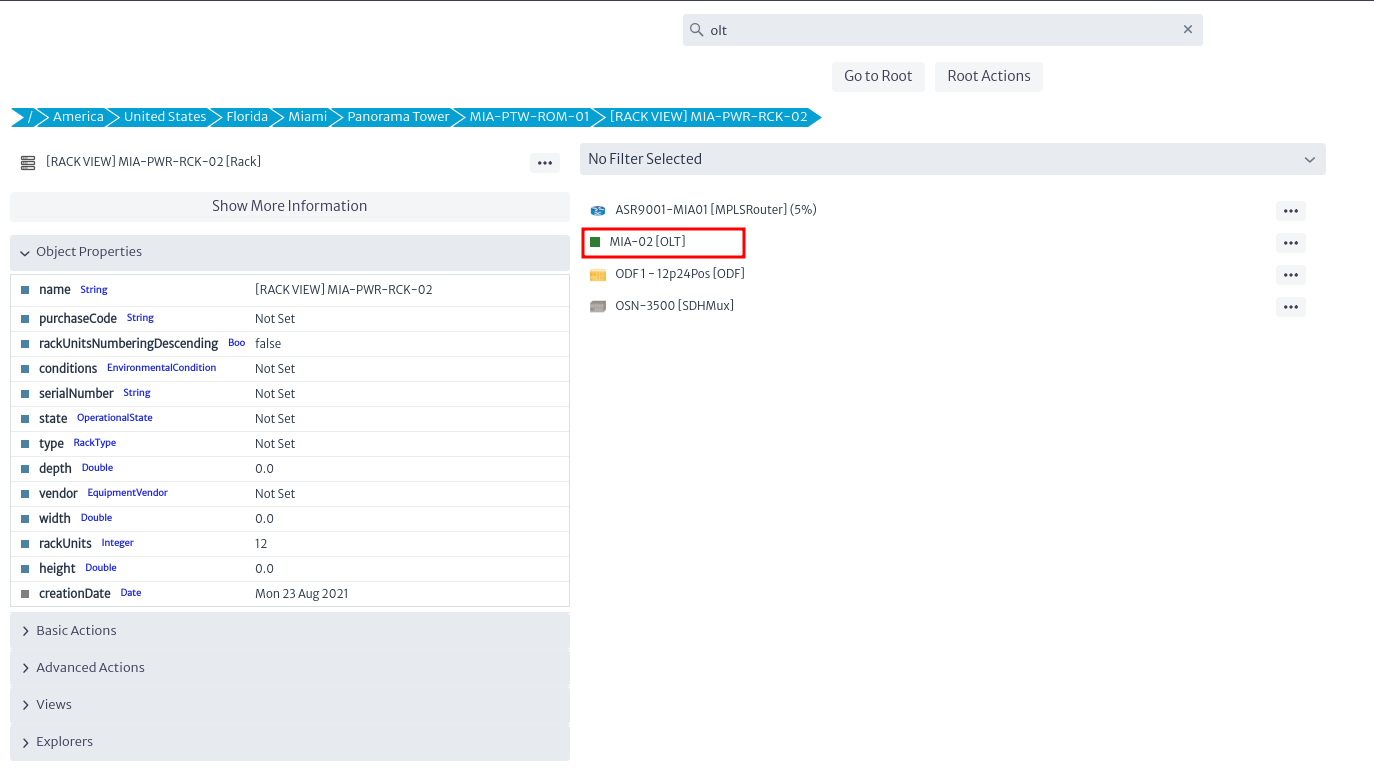
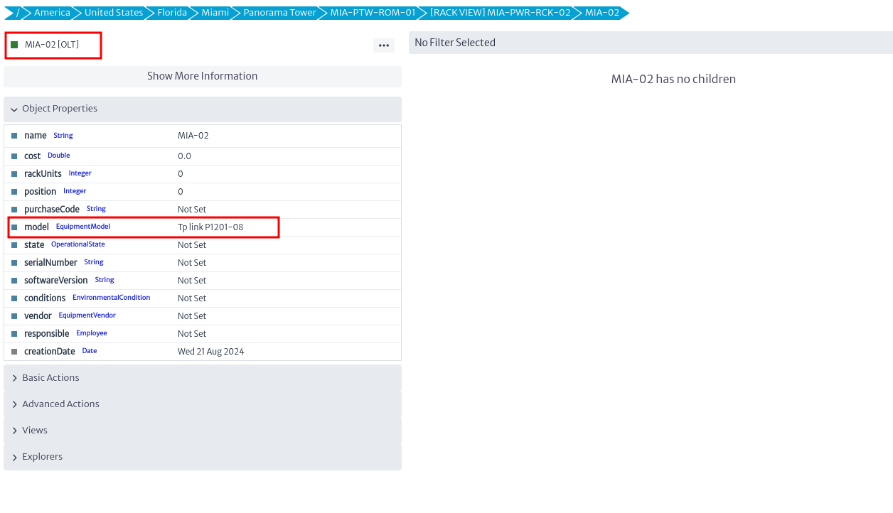
Once the design has been assigned to the list type, go to the Navigation module and search for one of the Rack available in the application, in which we will create a new OLT and assign the model Tp link P1201-08, as shown in Figure 34-35. For instructions on how to create elements, visit Navigation section.
 |
|---|
| Figure 34. New OLT |
 |
|---|
| Figure 35. New OLT model |
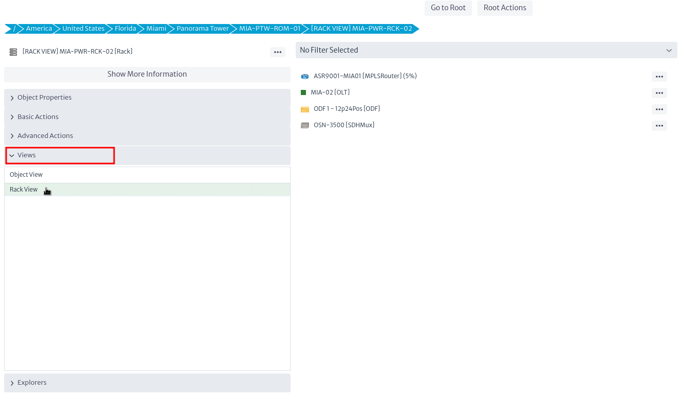
Next, to visualize the physical view of the distribution of the elements, go to the menu view and select Rack View, as shown in Figure 36.
 |
|---|
| Figure 36. Rack view option |
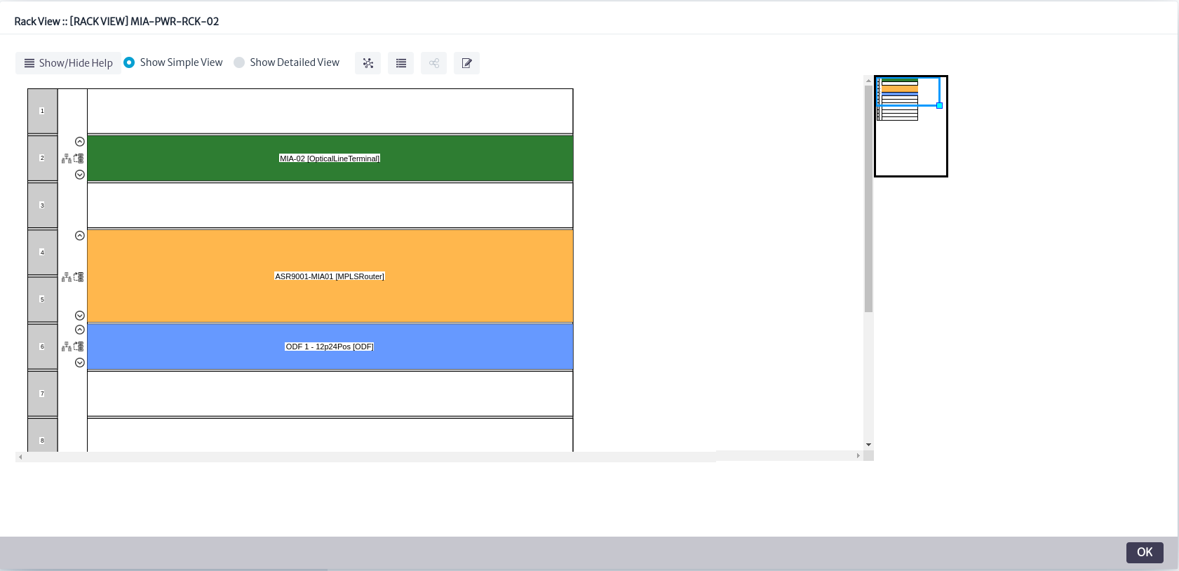
Upon doing this, the window in Figure 37 will open, where you can see how the elements are placed in the Rack. The distribution of the elements depends on the position and rack units assigned. Visit Rack View for more details on these configurations.
 |
|---|
| Figure 37. Rack view window |
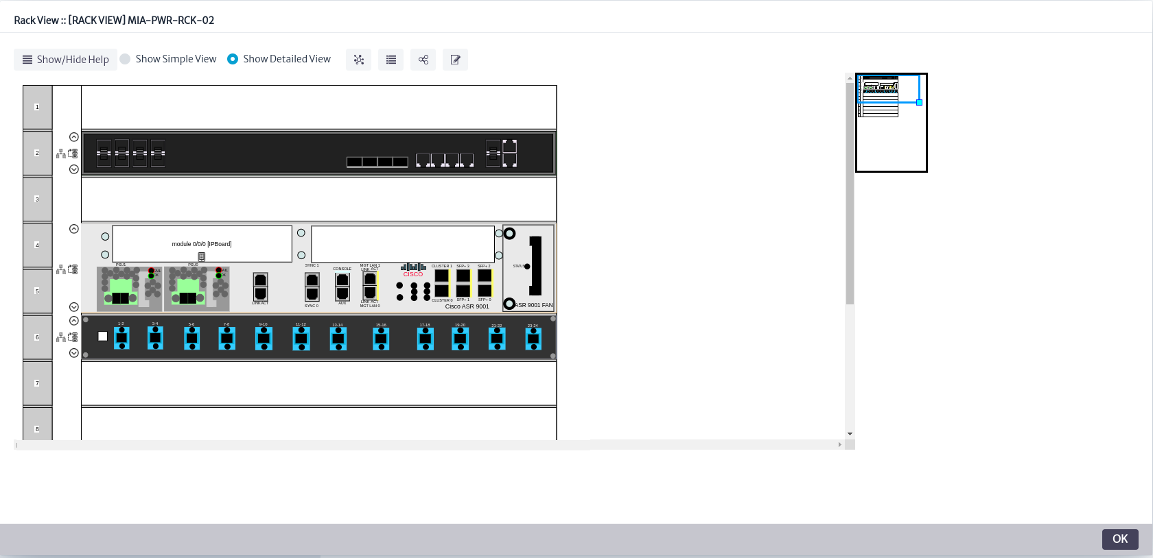
In the previous figure, you can see the elements assigned to the rack. However, this view only allows you to observe the rack slot assigned to the elements and the number of slots they occupy. As shown, the OLT is represented in green in the first unit of the Rack. The Rack View offers a more detailed view of the elements. To access this, select the Show Detailed View option, which will display the designs assigned that have been created in the Layout Editorr, as shown in Figure 38.
 |
|---|
| Figure 38. Detailed view |
With this, we have completed the design of the OLT in the application. Additional functions and configurations available in the Rack View can be consulted in the Rack View section.